FAME (Federation Architecture)
The Federation Architecture Modeling Environment (FAME) is the central workspace for designing and managing your HLA federation structure. It allows you to define federate applications, link them to RTI settings, and associate them with specific Object Models.
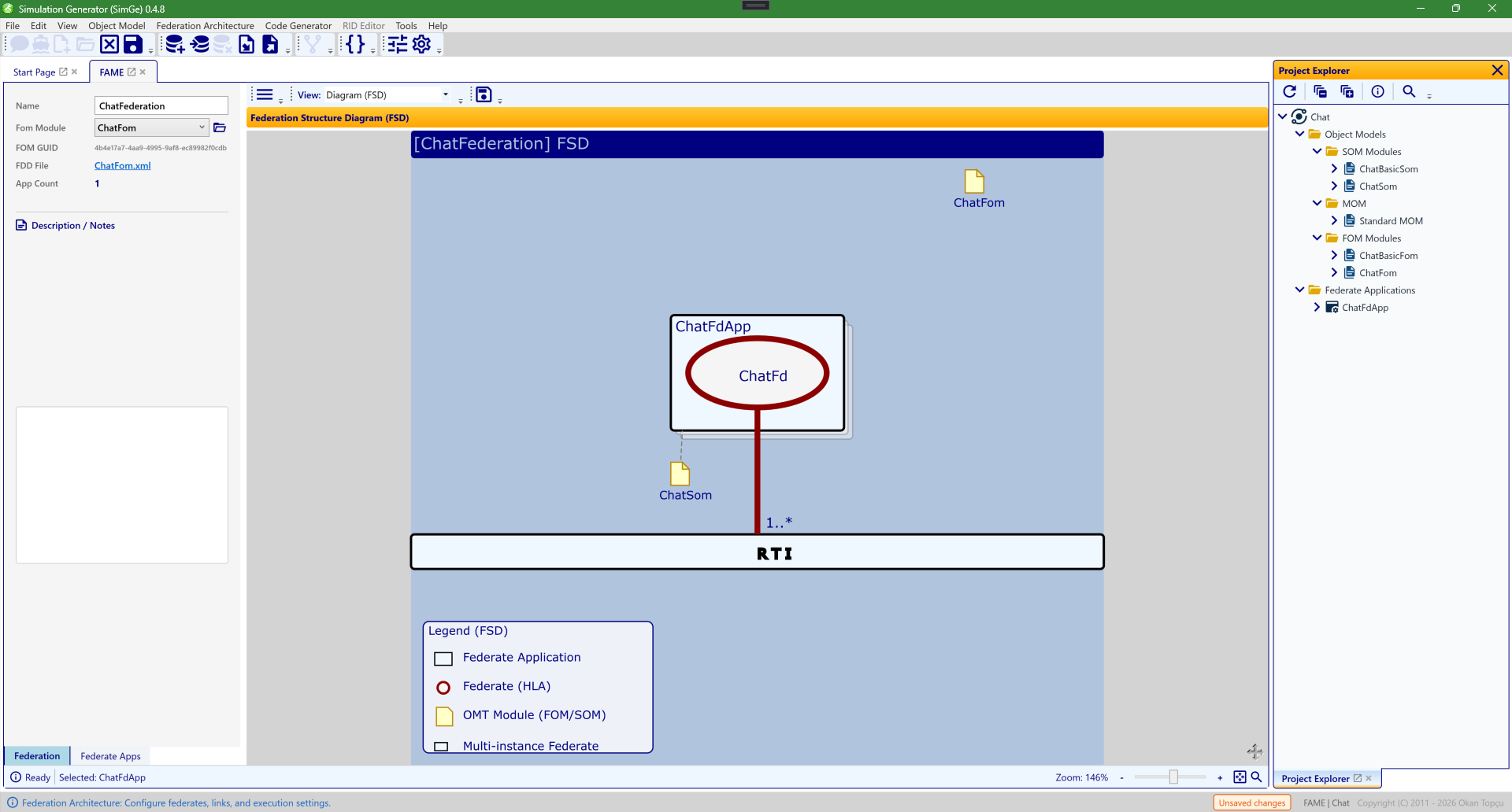
The FAME workspace showing the Chat federation in the Federation Structure Diagram (FSD) view (chosen from the View dropdown). The federate application ChatFdApp (containing the ChatFd federate) links to its ChatFom / ChatSom modules with 1..* multiplicity and connects to the central RTI. The properties pane on the left configures the federation and the selected federate; double-clicking a federate's note icon jumps to its Object Model Editor.
Workspace Layout
The FAME interface is divided into three main areas: 1. Main Toolbar: Common operations like toggling the property pane and exporting the diagram. 2. FSD Diagram (Center): A visual representation of the architecture. 3. Properties Pane (Left): Configuration tabs for the Federation and individual Federate Applications.
The Federation Tab
This tab contains global settings for the entire federation execution.
- Federation Name: The identifier for the federation execution.
- Fom Module: Select the root FOM module for the federation.
- Click the Folder (Open) icon next to the dropdown to immediately jump to that module's Object Model Editor (OME).
- FOM GUID: Displays the unique identifier of the selected FOM module.
- FDD File: Shows the path where the Federation Design Document (FDD) is generated. Clicking the link opens the folder in Windows Explorer.
The Federate Apps Tab
Manage individual simulation components (federate applications) here.
Toolbar Actions
Located at the top of the tab: - ➕ Add: Creates a new federate application and automatically focuses the App Name field. - 🗑️ Remove: Deletes the selected application. This button is automatically disabled if no applications exist. - { } Generate Code: Scaffolds the source code for the selected federate using the active code generator template.
Application Properties
- App Name: The C#-compatible name for the application class.
- Som Module: Select the SOM module associated with this federate.
- Click the Folder (Open) icon to jump to its OMT editor.
- SOM GUID: Displays the unique identifier of the linked SOM module.
- Federate Name & Type: HLA-specific naming for the federate execution.
- Multiplicity: Defines how many instances of this federate will exist in the federation (e.g.,
0..1,1..*,5). - Connection: Technical RTI connection string (e.g.,
localhost:6001). - Notes: Personal documentation and implementation details for the federate.
Interactive FSD Diagram
The Federation Structure Diagram (FSD) is a "living" model that provides real-time feedback.
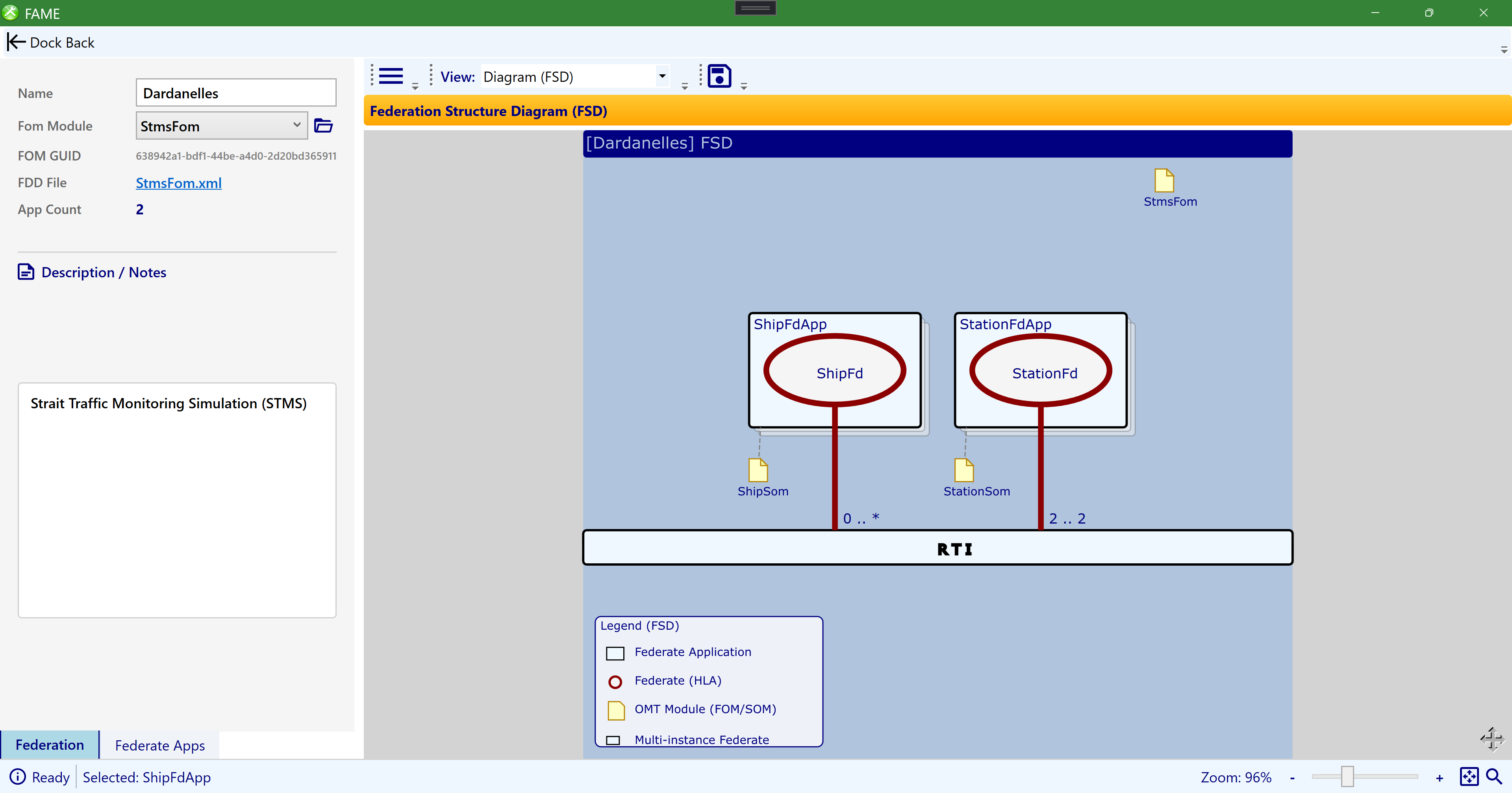
The interactive FSD (here the STMS sample's Dardanelles federation). The federate applications ShipFdApp and StationFdApp link to their SOM modules and to the central RTI, annotated with multiplicity (0..*, 2..2); the StmsFom module appears top-right. Connection lines glow on hover, health badges flag modeling issues, multi-instance federates render as stacked boxes, and a legend in the bottom-left explains the symbols.
Visual Indicators
- Stacked Boxes: If a federate's multiplicity is greater than one, it appears as a stack of boxes to indicate a multi-instance cluster.
- Interactive Pulse: Hovering over a federate box or its "Lollipop" icon makes the connection line to the RTI glow and thicken, representing an active link.
- Rich Tooltips: Hover over any federate box to see a human-readable summary of its connection settings (Target, Port, Protocol), multiplicity, and linked modules.
- Legend: A guide in the bottom-left corner explains the symbols used in the diagram (FdApp, Federate, OMT Module, Multi-instance).
Navigation
- Interactive Navigation: Double-click a module's "Note" icon to jump straight to that module's Object Model Editor.
- Selection Sync: Clicking a federate box selects and focuses that federate in the properties pane.
Health Diagnostics
Diagnostic badges appear in the top-right corner of federate boxes to catch modeling errors early: - 🛑 Critical (Red): Severe errors like invalid names that would break code generation. - ⚠️ Warning (Orange): Missing required associations like a SOM Module. - ℹ️ Information (Gray): Optional fields like connection settings are empty.
Deployment Diagram (UML)
Switch the View dropdown from Diagram (FSD) to Deployment Diagram (UML) to see the same federation as a UML deployment diagram — useful for documenting how the federation maps onto physical hosts and the network.
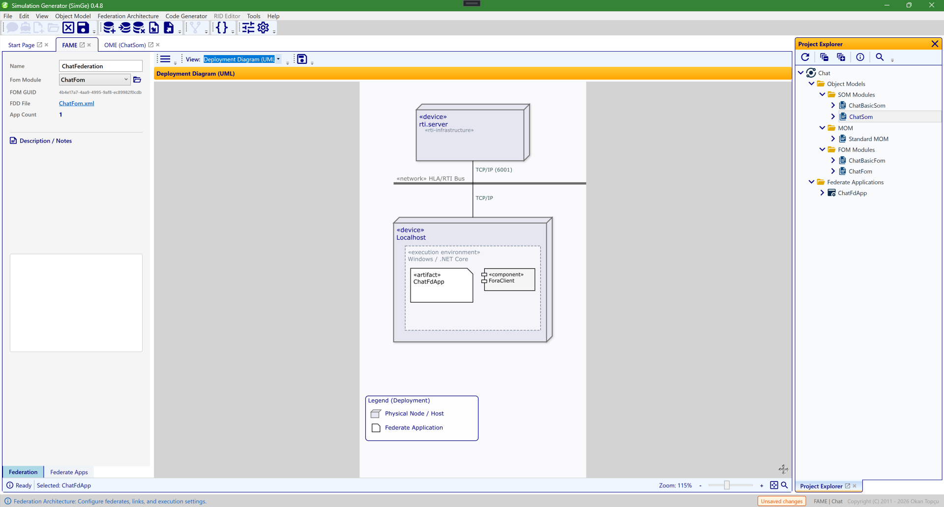
The Deployment Diagram (UML) view of the Chat federation. UML «device» nodes — an rti.server «infrastructure» node and a Localhost node with a Windows / .NET Core «execution environment» — are joined by the «network» HLA/RTI Bus over TCP/IP (port 6001). The federate is shown as an «artifact» (ChatFdApp) together with its «component» (ForaClient). A legend in the bottom-left explains the node and federate symbols.
Status Bar Controls
Located at the bottom of the workspace: - Status Message: Shows current system activity or "Ready" state. - Selection Info: Displays the name of the currently selected federate application. - Zoom Controls: * Slider: Smoothly adjust diagram magnification from 20% to 250%. * +/- Buttons: Step-wise zoom adjustment. * Fit-to-Window: Click the square frame icon to instantly scale the entire diagram to fit the screen.